Thursday, 24 May 2012


EXHAUST 


-Today the class and i looked at the falcon to check why the car is not idling properly.We found out that their was a leak by the manifold. The car was running to lean, so Hans sprayed some CRC so we could hear the leak and where it was coming from.

-We used the pressure gauge to force the pressure of the leak so we could hear where the problem is.


Petrol Emissions

-What could a really clean vehicle exhaust emission look like?

IDLE     -           2500 RPM

HC-  1ppm -      5ppm
CO- 0.04% -     0.01%
CO2- 15.5-      15.4%
O2- 0.1%-         0.1%

-What could a RICH vehicle exhaust looks like?

IDLE

HC-148 ppm
CO-5.67%
CO2-11.3%
O2-0.2%
GLOW PLUG!


One big difference between a diesel engine and a gas engine is in the injection process. Most car engines use port injection or a carburetor. A port injection system injects fuel just prior to the intake stroke (outside the cylinder). A carburetor mixes air and fuel long before the air enters the cylinder. In a car engine, therefore, all of the fuel is loaded into the cylinder during the intake stroke and then compressed. The compression of the fuel/air mixture limits the compression ratio of the engine -- if it compresses the air too much, the fuel/air mixture spontaneously ignites and causes knocking. Because it causes excessive heat, knocking can damage the engine.


Today, in class we took out the glow plugs out and tested them to see if they were all working or not.They way we tested them is we put them on the bench and got a jumper pack, putting the negative one ground and the positive on the glow plug. after a few seconds the glow plug lit up and turned bright red as in photos.
If it does not glow then u would need to change your glow plugs, but another easier way to check your glow plugs is by using a voltmeter. 


Diesel ignition timing (mechanically controlled injection)
Diesel engines ignite the fuel using the heat created by high compression (does not have spark plugs). The timing of the engine is controlled by the fuel injected into the cylinders if the fuel is injected to early the timing will be premature and if it is too late the timing will be retarded both resulting in a lack of power.

Experiment 


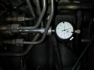
We set the timing for a Mazda diesel engine. First we loosened the bolt, in the middle of the four high pressure lines that go to the injectors, on the diesel pump and put the DTI gauge in its place. Then we turned the crankshaft to 30 degrees before T.D.C and zeroed the Gauge. Then we turned the crankshaft to 2 degrees after T.D.C. We then loosened the diesel pump so that it was able to pivot, moved it so that the reading on the Gauge matched up with specifications and then tightened the diesel pump again. We removed the DTI gauge  and replaced the bolt.

Reflection


The diesel pump from the engine we worked on is very similar to the distributor on most petrol engines as far as timing goes. The method we used is called static timing (engine is stationery


diesel engine: mode of operation


1. Suction stroke: Pure air gets sucked in by the piston sliding downward.


2. Compression stroke: The piston compresses the air above and uses therby work, performed by the crankshaft.


3. Power stroke: In the upper dead-center, the air is max. compressed: Pressure and Temperature are very high. Now the black injection pump injects heavy fuel in the hot air. By the high temperature the fuel gets ignited immediately (autoignition). The piston gets pressed downward and performes work to the crankshaft.


4. Expulsion stroke: The burned exhaust gases are ejected out of the cylinder through a second valve by the piston sliding upward again.


Wednesday, 16 May 2012


OSCILLOSCOPE!


What does an oscilloscope do?

An oscilloscope is easily the most useful instrument available for testing circuits because it allows you to see the signals at different points in the circuit. The best way of investigating an electronic system is to monitor signals at the input and output of each system block, checking that each block is operating as expected and is correctly linked to the next. With a little practice, you will be able to find and correct faults quickly and accurately.


An oscilloscope is an impressive piece of kit:


which way the volts and time go:

screen

-Today in class we use the Oscilloscope to show the reading of the sensor.the sensor showed a positive
reading and there was nothing wrong with it, the reading was about 12.7 mv which is a normal average reading.

2 V calibration signal


- The reading we got to check the TPS looked like this ,


Injectors

In an injector there are solenoid that is controlled by the ECU according to the engine's timing. When the solenoid receives power it opens up to allow the pressured fuel in the fuel rail to squirt into the cylinders. The  coil in the solinoid has resistance that according to ohm's law it means the volts should go down (as shown in the picture below) when the power is removed the voltage goes back up but it is noted that there is a voltage spike, a voltage spike occurs when a magnetic field collapses.


Oxygen sensor

The oxygen sensor voltage oscillates up and down when the car is idling. When the engine speed is increased the voltage will oscillate slower.


Tuesday, 15 May 2012


ELECTRICAL COMPONENT  SENSORS


AFP= Air/ fuel  ratio.
AfS= Air/ fuel ratio sensor.
CEL= Check engine light.
COP= Coil on plug.
CTS= Coolant temperature sensor.
DIS=Distributorless Ignition systems.
DTC= Diagnostic trouble code.
ECM= Engine control module.
ECT= Engine coolant temperature.
ECU= Engine control unit.
EFI= Electronic fuel injections.
EFIE= Electronic fuel injection Enhancer.
EOP= Engine oil pressure sensor.
HEGO= Heated exhaust gas oxygen sensor.
IAT= Intake air temperature sensor.
MAF= Mass air flow sensor.
MAP= Manifold absolute pressure.
MAT= Manifold air temperature.
MIL= Malfunction Indicator Light.
MMW=Milliliters per Minute per Watt.
O2S= Oxygen sensor.
OBD-2= On board Diagnostic system.
PCM= Powertrain Control module.
PCV= Positive Crankcase Ventilatio.
TPS= Throttle position sensor.
VCM= Vehicle control module.
VSS= Vehicle speed sensor.
WOT= Wide open throttle sensor.


NOTE:
- Less vacuum= more pressure.
- kilo pascal's KPA 100 KPA=1 Atmosphere.
- Cranking turns engine slower so there us less vacuum.
- Cranking the throttle open will have very little or no vacuum/


Outline: On- car Fuels Practical


Review four stroke cycle
Engine conditions, engine needs:
Rich, lean
cranking, cold, idle, cruise, power, deceleration

Basic:
what it takes to make a engine run.

-Mechanical: Pistons, cam,valves,belts. etc
-Fuel: pump,flow,injections, sensors, ECU
-Air/ exhaust: idle speed ,CAT,EGR,PCV, etc
-Ignition: Spark.plugs,timing, igniters,Ht leads,etc


fuel injector system


Fuel pressure
The fuel pump, pumps the fuel from the fuel tank through the filter to the fuel rail and then into the cylinders via the injectors. The pressure of the fuel is controlled by the fuel pressure regulator on the end of the fuel rail. The fuel pressure regulator works with vacuum from the engine. The faster the engine goes the less vacuum it creates in the manifold which means that the regulator would be closed more. When the regulator closes it creates a higher pressure in the fuel line (by restricting the flow or blocking off the fuel at the end of the fuel rail)  which forces more fuel through the injectors into the cylinder.

Experiment

We connected a fuel pressure gauge to the fuel line after the filter. We started the engine and checked the gauge the reading was about 2.5 bar when we revved the engine the pressure increased to about 3 bar. To simulate the engine at full speed the vacuum hose can be disconnected from the fuel pressure regulator.

Reflection

The fuel pressure gauge can be used to see if the fuel pump is working and to check if the fuel pressure regulator is working properly. when the engine is idling and then the regulator vacuum hose is removed the pressure should increase in the fuel line. If it remains the same there may be a problem with the fuel pressure regulator.


Thursday, 10 May 2012

Oxygen sensor


wire installation on vehicle:

red wire:12v source e.g 12v ignition or 12v ACC.not 12v battery! (it shouldn't stay on when the key is removed.)

Black wire:ground source. any ground source will do as all ground connections should be the same.

green wire: signal wire. this must go to the oxygen sensor's signal out, in parallel with the ECU. not in series!
(this is usually a blue or black wire). If your not sure which wire is the signal wire, then just put a multimeter on at a time until you measure a wire that has a voltage range of OV-1V

NOTE: this unit will only work with a narrow band oxygen sensor (OV-1V)

background:

This display unit is designed to show an oxygen sensor's voltage reading which it obtains from the air/fuel mixture after combustion . It does this by lighting up LEDs to show the different conditions of air/fuel mixture.

It uses an "IC' chip called the LM324 comparator. This chip compares the voltage from the oxygen sensor to a preset voltage from the resistors on the pcb.

Basically the series resistors have two voltages which it uses to compare it with the O2 sensor Voltage.

This being 0.23V and 0.63V.

This following is a comparison is to show what will happen at different conditions of the sensor voltage.


Oxygen sensor's                         Led colour:                      Air/fuel ratio
voltage:

Less the 0.23V                            green                             Lean
between 0.23V & 0.63V             yellow                           stoich (14.7:1)
Above 0.63 V                             red                                Rich


A basic guide on the LED sequence:

Initial start-up= green led. This is simulating a lean condition as the O2 sensor can't produce a voltage yet because it hasn't warmed up enough.However there are ECU's that send out a voltage to the O2 sensor
at initial start-up to simulate the actual rich condition when cold.

After 10sec-3mins=red LED.Depending if it's a heated O2 sensor or non-heated it should gradually start to go from green to yellow and then to red and stay on red.This is because the engine runs rich when it's cold.

After 4mins-7mins= all LEDs.again depending on if it's a heated or non heated O2 sensor, the system should  gradually go into closed loop as the engine warms up.And then the engine will cycle from lean to rich lighting up each LED in sequence.

Full acceleration=red LED. With the throttle fully open,the red LED will as it's indicating a rich mixture.

Deceleration= greed LED.after letting go the throttle from full throttle , the system should go learnas the injectors should be squirting in a very low amount of fuel or none at all.


Tuesday, 8 May 2012


Different types of engine


-OHC or SOHC engine


SOHC engine animated diagram 


OHC in general means OverHead Cam while SOHC means Single Over Head Cam.
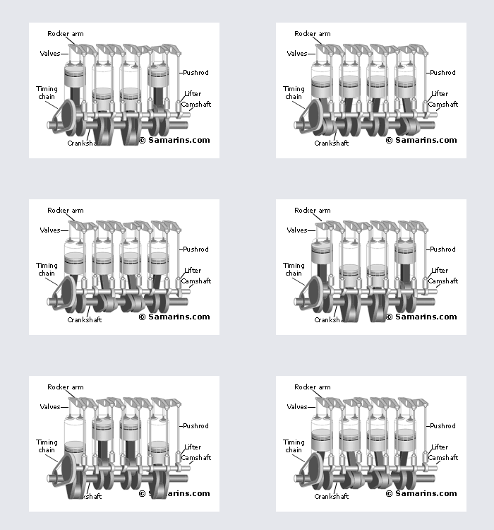
In a SOHC engine the camshaft is installed in the cylinder head and valves are operated either by the rocker arms or directly through the lifters (as in the picture).
The advantage is that valves are operated almost directly by the camshaft, which makes it easy to achieve the perfect timing at high rpm. It's also possible to install three or four valves per cylinder
The disadvantage is that an OHC engine requires a timing belt or chain with related components, which is more complex and more expensive design.


-DOHC or Twin Cam engine


DOHC engine animated diagram
DOHC means Double OverHead Cam, or sometimes it could be called "Twin Cam". A DOHC setup is used in most of newer cars. Since it's possible to install multiple valves per cylinder and place intake valves on the opposite side from exhaust vales, a DOHC engine can "breathe" better, meaning that it can produce more horsepower with smaller engine volume. Compare: The 3.5-liter V6 DOHC engine of 2003 Nissan Pathfinder has 240 hp, similar to 245 hp of the 5.9-liter V8 OHV engine of 2003 Dodge Durango.
Pros: High efficiency, possible to install multiple valves per cylinder and adopt variable timing.
Cons: More complex and more expensive design.


-OHV engine design


OHV engine animated diagramOHV means OverHead Valve - an engine design where the camshaft is installed inside the engine block and valves are operated through lifters, pushrods and rocker arms (an OHV engine also known as a "Pushrod" engine). Although an OHV design is a bit outdated, it has been successfully used for decades. An OHV engine is very simple, it has more compact size and is proven to be durable.

On the downside, it's difficult to precisely control the valve timing at high rpm due to higher inertia caused by larger amount of valve train components (lifter-pushrod-rocker arm). Also, it's very difficult to install more than 2 valves per cylinder, or implement some of the latest technologies such as Variable Valve Timing - something that could be easily done in a DOHC engine.


Thursday, 3 May 2012

Radiators 


-On a radiator cap there is 2 seals and 2 valves to hold the pressure and closes and opens when the water/coolant is hot or cold.


A radiator is a type of heat exchanger. It is designed to transfer heat from the hot coolant that flows through it to the air blown through it by the fan.

Most modern cars use aluminum radiators. These radiators are made by brazing thin aluminum fins to flattened aluminum tubes. The coolant flows from the inlet to the outlet through many tubes mounted in a parallel arrangement. The fins conduct the heat from the tubes and transfer it to the air flowing through the radiator.

The tubes sometimes have a type of fin inserted into them called a turbulator, which increases the turbulence of the fluid flowing through the tubes. If the fluid flowed very smoothly through the tubes, only the fluid actually touching the tubes would be cooled directly. The amount of heat transferred to the tubes from the fluid running through them depends on the difference in temperature between the tube and the fluid touching it. So if the fluid that is in contact with the tube cools down quickly, less heat will be transferred. By creating turbulence inside the tube, all of the fluid mixes together, keeping the temperature of the fluid touching the tubes up so that more heat can be extracted, and all of the fluid inside the tube is used effectively.


Heater
-A system of valves or baffles, or both, is usually incorporated to simultaneously operate a small radiator inside the vehicle. This small radiator, and the associated blower fan, is called the heater core, and serves to warm the cabin interior. Like the radiator, the heater core acts by removing heat from the engine. For this reason, automotive technicians often advise operators to turn on the heater and set it to high if the engine is overheating.
Temperature control

Water-flow control

Car engine thermostat
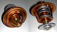
-The engine temperature is primarily controlled by a wax-pellet type of thermostat, a valve which opens once the engine has reached its optimum operating temperature.
When the engine is cold, the thermostat is closed except for a small bypass flow so that the thermostat experiences changes to the coolant temperature as the engine warms up. Engine coolant is directed by the thermostat to the inlet of the circulating pump and is returned directly to the engine, bypassing the radiator. Directing water to circulate only through the engine allows the temperature to reach optimum operating temperature as quickly as possible whilst avoiding localised "hot spots." Once the coolant reaches the thermostat's activation temperature, it opens, allowing water to flow through the radiator to prevent the temperature rising higher.

-Once at optimum temperature, the thermostat controls the flow of engine coolant to the radiator so that the engine continues to operate at optimum temperature. Under peak load conditions, such as driving slowly up a steep hill whilst heavily laden on a hot day, the thermostat will be approaching fully open because the engine will be producing near to maximum power while the velocity of air flow across the radiator is low. (The velocity of air flow across the radiator has a major effect on its ability to dissipate heat.) Conversely, when cruising fast downhill on a motorway on a cold night on a light throttle, the thermostat will be nearly closed because the engine is producing little power, and the radiator is able to dissipate much more heat than the engine is producing.


- Allowing too much flow of coolant to the radiator would result in the engine being over cooled and operating at lower than optimum temperature. A side effect of this would be that the passenger compartment heater would not be able to put out enough heat to keep the passengers warm. The fuel efficiency would also suffer.The thermostat is therefore constantly moving throughout its range, responding to changes in vehicle operating load, speed and external temperature, to keep the engine at its optimum operating temperature.


How to check the hoses


Find both of your radiator hoses. One reason radiator hoses are overlooked during a routine car inspection is that the hoses can be difficult to reach.

Image:Check Radiator Hoses Step 1.jpg


.


 Visually inspect each radiator hose. Hoses should not be swollen or cracked, both of which could lead to a failure.


Image:Check Radiator Hoses Step 2.jpg


Perform a squeeze test. While the engine is warm after a drive, squeeze the radiator hoses, paying particular attention to areas where the hose bends.


Image:Check Radiator Hoses Step 3.jpg


Check the clamps that connect the hose to the radiator and the engine. There are 3 different types of radiator hose connections, gear clamps, banded clamps and wire clamps.


Image:Check Radiator Hoses Step 4.jpg


Warnings

Never remove a hot radiator cap. Pressure built up inside the radiator can cause boiling coolant to gush out of the radiator, causing severe burns


Things You'll Need


Flashlight, for inspecting the hoses underneath the engine
Screwdriver, for tightening clamps, if necessary
Hose clamp pliers, for adjusting wire clamps, if necessary


Monday, 2 April 2012

ENGINE
                    

HEAD:

 what is a cylinder head?

 -The detachable metal casting that fits onto the top of a cylinder block. In an engine it contains part of the combustion chamber and in an overhead-valve four-stroke engine it houses the valves and their operating mechanisms.


Whats inside a cylinder head?


WATCH VIDEO !!!!!


Theory background:  
-Seals the top of the cylinder,houses the valves,which control the flow of air fuel into the cylinder and the burned up gases out of the cylinder.

Experiment:
- Today we learnt how to measure the head by using a precision striaght edge and feeler gauge,measure the head face surface for WARPAGE. We had to check every side of the head to see if it had any gaps for leakage, to do that .We put the striaght edge on the cylinder head and the tourch behind the straight edge.If we saw any light , that means the cylinder head has a gap which is no good.


Reflection:

- Today we learnt that the cylinder head is made out of aluminum, thats valuvs are different to what i expected. I did not know how to measure the vaulves by using a micrometer and also, measuring the head with a straight edge to see if there is any gap.To see if the head will leak or not by seeing if the light form the other side will show up.


Whats the difference between diesel and petrol head?


 THE BLOCK


The engine block is the linchpin of vehicles which run on internal combustion, providing the powerhouse for the vehicle. The engine block is termed a block because it is usually a solid cast car part, housing the cylinders and their components inside a cooled and lubricated crankcase. The engine block is designed to be extremely strong and sturdy, because failure of the engine block results in failure of the car, which will not function until the engine block is replaced or repaired.


The engine block is typically made of cast iron, although in the late 1990s engine blocks made from plastic and other experimental materials were being used in prototype cars with the hope of developing more lightweight, efficient vehicles. A cast iron engine block can comprise a substantial portion of the weight of the car, and usually requires multiple people to be removed and worked on safely.

Working from the outside in, the engine block starts with a solid metal outside, designed to seal everything inside. A number of channels and passages inside comprise the cooling jacket, and are designed to deliver water from the radiator to all the hot sections of the engine, preventing overheating. After the water is circulated in the engine, it returns to the radiator to be cooled by the fan and sent back through the engine.


P13476 Image Large P13486 Image Large
P13465 Image Large


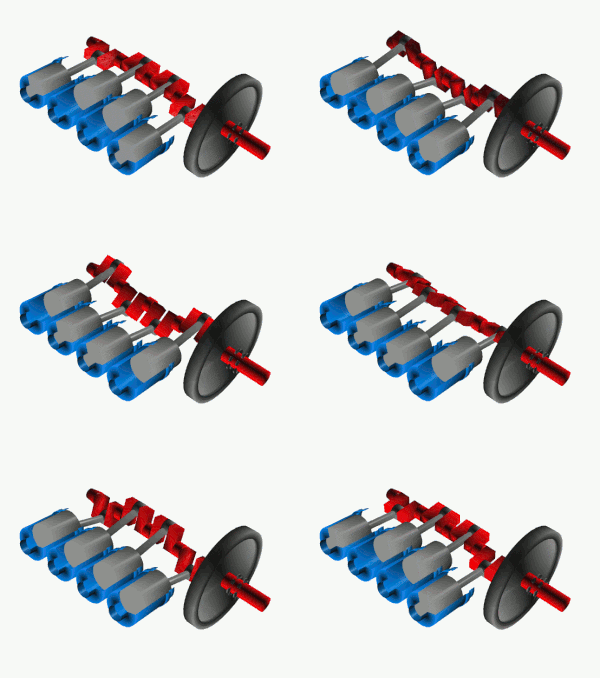
The crankshaft, sometimes casually abbreviated to crank, is the part of an engine that translates reciprocating linear piston motion into rotation. To convert the reciprocating motion into rotation, the crankshaft has "crank throws" or "crankpins", additional bearing surfaces whose axis is offset from that of the crank, to which the "big ends" of the connecting rods from each cylinder attach.
It typically connects to a flywheel, to reduce the pulsation characteristic of the four-stroke cycle, and sometimes a torsional or vibrational damper at the opposite end, to reduce the torsion vibrations often caused along the length of the crankshaft by the cylinders farthest from the output end acting on the torsional elasticity of the metal.


P13483 Image Large

  Piston stroke
The distance the axis of the crank throws from the axis of the crankshaft determines the piston stroke measurement, and thus engine displacement. A common way to increase the low-speed torque of an engine is to increase the stroke, sometimes known as "shaft-stroking." This also increases the reciprocating vibration, however, limiting the high speed capability of the engine. In compensation, it improves the low speed operation of the engine, as the longer intake stroke through smaller valve(s) results in greater turbulence and mixing of the intake charge. Most modern high speed production engines are classified as "over square" or short-stroke, wherein the stroke is less than the diameter of the cylinder bore. As such, finding the proper balance between shaft-stroking speed and length leads to better results.
Pistons
Engine Oil Pan


The oil pan is located at the bottom of the engine, and on most cars and trucks is used to hold the engines oil. Most cars will have wet sump-oiling system where engine oil is kept underneath the engine in an oil pan. Typically a oil pan will be made of steel or aluminum and hold 3-10 quarts of oil for lubricating the engine. The oil pan generally gets deeper the farther back it goes. This is to keep a supply of oil ready for the oil pump when the car is accelerating, braking or cornering.

The quantity of oil the oil pan holds is usually related to engine size. Larger displacement engines will have a larger oil capacity and will need a larger oil pan. While you normally would not think of an oil pan needing replacement there are reasons where you would need to do so. You may need a new oil pan if yours has had the oil drain plug stripped, has gotten dented or has been punctured.

Some enthusiasts choose to upgrade their oil pan to a higher capacity, aluminum type. This helps to dissipate heat and keeps oil ready for the oil pump to use even under extreme driving conditions. These oil pans are mostly used for racing. Most consumers simply purchase a stock OEM, genuine or aftermarket oil pan. Installing a new oil pan is a pretty basic job and most should be able to perform this job at home with common hand tools. Labor on this job is not very expensive if you are unable to do this yourself.